

Integrated Asset Management (IAM) workflows integrate subsurface reservoir models and surface production networks, allowing engineers to bring under control the rapidly expanding asset complexity due to increasing amount of captured data. While consolidation of acquired & processed data continues to improve, IAM Workflows continue to face problems with providing an integrated platform for dynamic reservoir simulation models and surface facilities.
Modern digital oil field (DOF) systems can’t survive without comprehensive solutions that provide an all-in-one outlook for assets’ performance for management. State-of-the-art systems are required to address operational challenges, perform root-cause analysis, identify bottlenecks and understand system limitations. Furthermore, high-end modelling is must to effectively quantify the plethora of data collected over the field.
Modern IAM workflows may be classified into several types, depending on how the subsurface modelling applications talk to the surface network systems, be it in terms of automation, types of coupling or level of interface.
Flow Table Coupling
Flowing bottom-hole pressure (BHP) is used as a function of flow rate for several parameters like wellhead pressure, gas-oil ratio, pressure-volume-temperature, etc. for well models. The information is stored within tables that capture liquid rate changes with pump frequency. Simulators are designed to use each table during the well’s life span or until the event is completed. While the simulator can run instantly, accuracy is sacrificed.
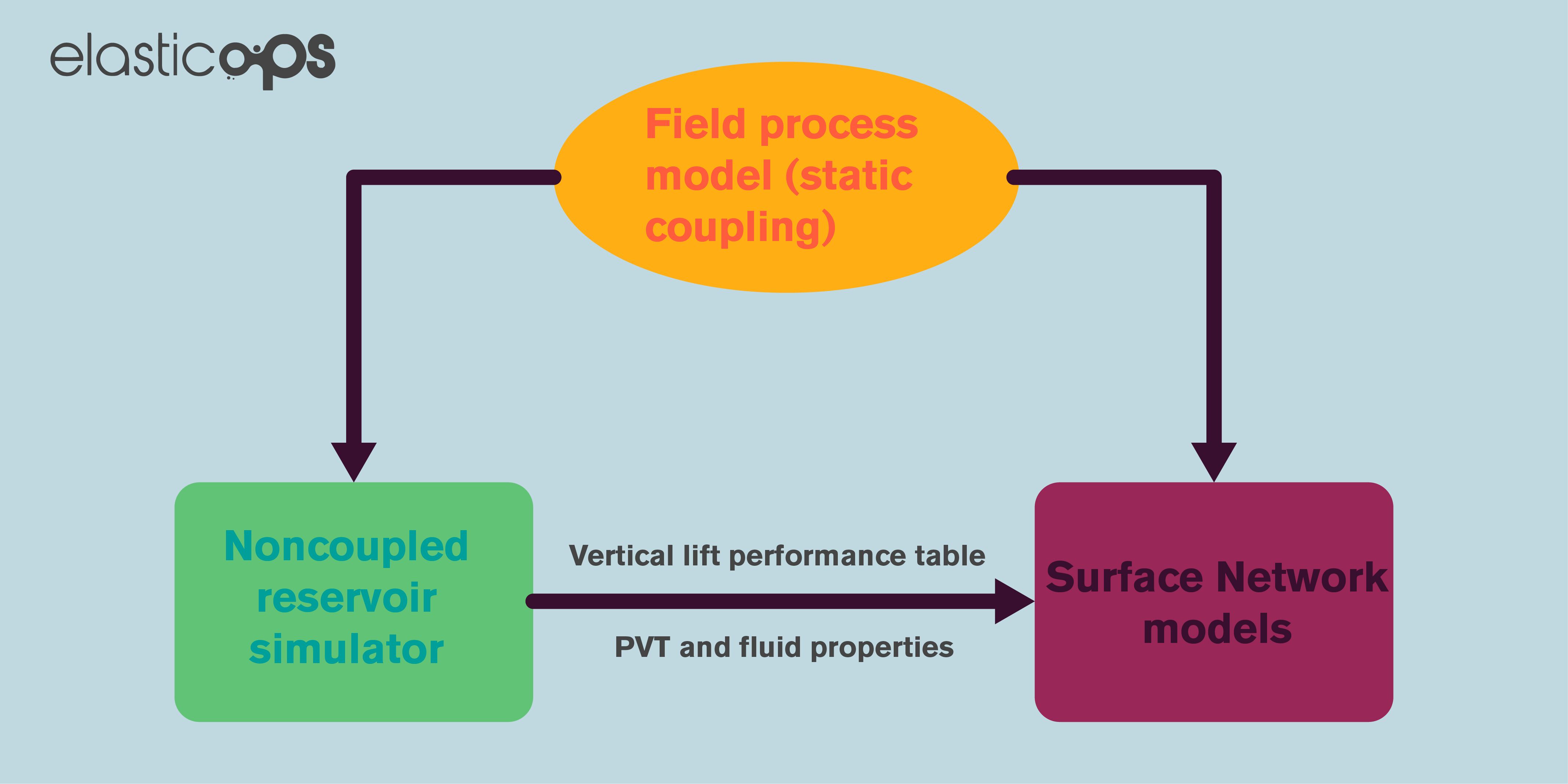
Static Coupling
A prior generation of reservoir performance tables are used for this workflow, comprising of oil, gas and water production rate forecasts over the set time horizon. The following diagram shows a workflow using static coupling, and while it is less accurate than dynamic coupling it is quite popular among operators.
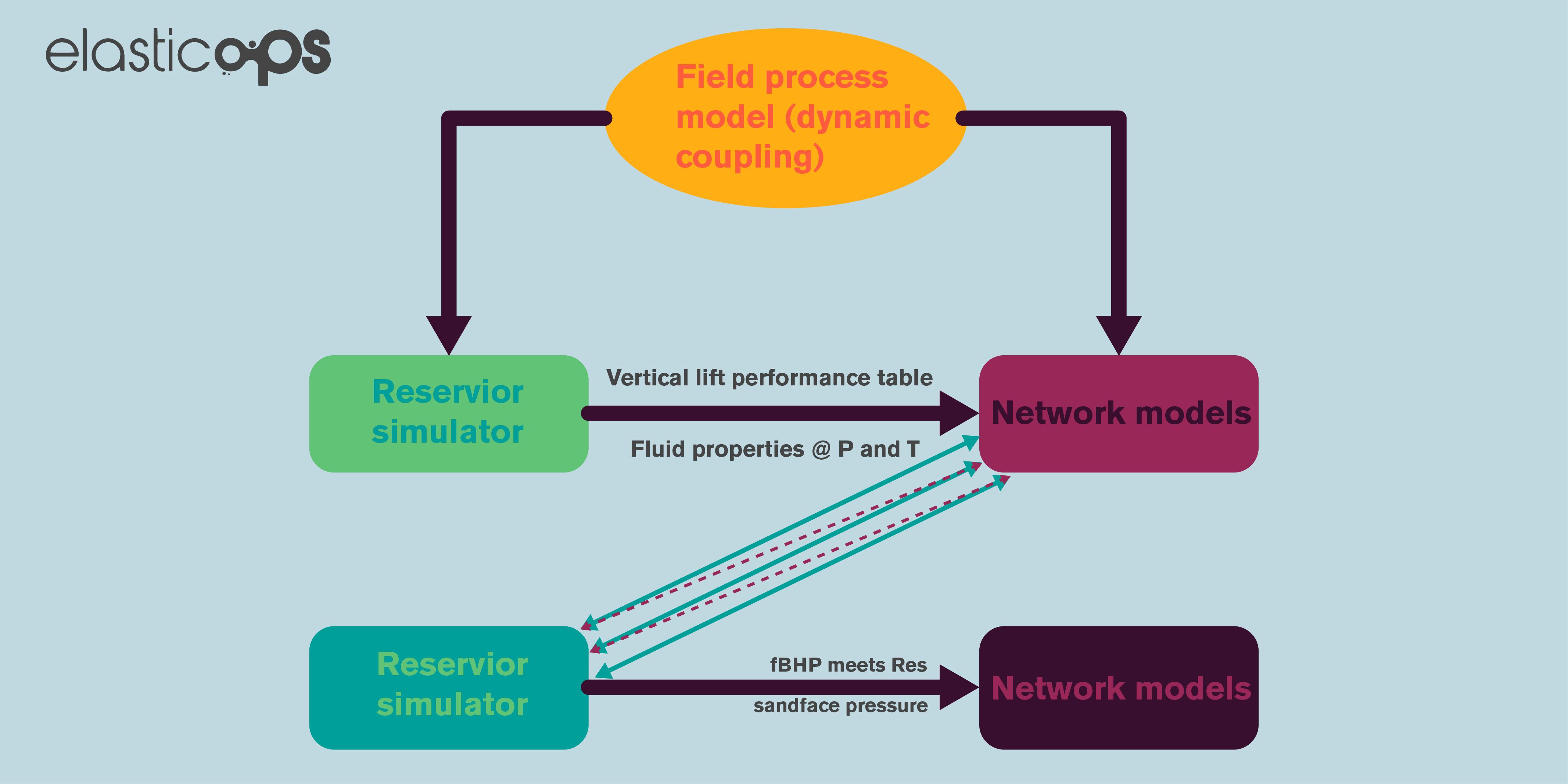
Dynamic Coupling
Also called loose coupling, involves the synchronous execution of reservoir and surface models. At every step of time, the reservoir model carries out a prediction of the production rates, which are fed into the surface models to generate well boundaries. These are then used by the reservoir model at the subsequent time step. The flowing BHP is predicted by the surface model and used by the simulator as a starting point of the convergence iteration.
Tight Iterative Coupling
This is an extension to the Dynamic Coupling method stated above, and adds accuracy to it through iteration. The method involves iteration between the pressure and flow boundaries at every time step, until convergence is obtained. While the coupling mode does add accuracy, it also has higher computational requirements. For instance, static coupling would require 10 minutes with a black oil reservoir model with 10 wells using 8 CPUs, while dynamic coupling would require 100 minutes, with tight coupling requiring more than 1000 minutes.
The graphs below compare production forecasts generated through static and dynamic coupling of a reservoir simulator and surface network. It can be seen that the forecasts generated by dynamic coupling is different than those generated by static coupling.
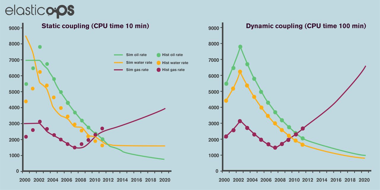
Dynamic coupling does hold the advantage of real-time updates to the model according to changing surface conditions, allowing a more realistic and accurate physical model to be drawn up. The effects of surface constraints become more enunciated when:
- The production is at near capacity
- The operating conditions are varying
- The simulation is being run over a longer period of time
Here’s an example of an IAM Workflow with tight iterative coupling:
The image above presents a clear direction as to how modern IAM workflows can be improved. Tight iterative coupling between surface network and subsurface models is imperative to enable seamless integration of assets within the field. The components shaded in green in the image above are tightly bounded, and coordinating with each other. These are:
Data Aggregation – This serves as a hub for gathering and summarizing data, and provides services such as quality assurance and control, so that statistical analysis may be carried out.
Visualization – The module provides real time data visualization such as trends, profiles and forecasts.
Workflow Process Controller – The component acts as a solid interface and control platform for dynamic coupling. This allows sophisticated well operations to be carried out such as artificial lift pumps, downhole ICVs and automated surface chokes.
Deploying the IAM Workflow with tight coupling does have its benefits. These include:
- Higher efficiency as processes are streamlined across multiple areas of operation
- More accurate production forecast
- Robust subsurface to surface integration, providing a solid foundation for future expansion
- Helps develop standardized automated workflows that can be improved over time
Applications for IAM and Associated Work Processes
The main purpose behind implementation of an IAM process is to instill optimization and cost-effectiveness within the workflow. The objective is achieved by taking into account a multitude of factors, like integration of realistic & variable production profiles, impact of system backpressure and real-time alterations in the environment. The IAM Workflow also provides a solid platform for engineers to raise the efficiency and bring timeliness into the production cycles.
An extension to the IAM framework is the IAMod workflow, which has a broader scope and involves monitoring, control and analysis of assets to improve performance and meet KPIs. It must be understood that IAM not only consists of simulation technologies but also multidiscipline interactions for effective decision making. The operational benefits are evident, and include but are not limited to shortening the learning curves of the staff, easier KPI validation, improved consistency and overall higher productivity.
For end users, IAM should ensure the provision of a transparent and clear interface for executing diverse workflows, from reservoir simulation to economic optimization. From the software implementation perspective, an IAM Framework must work towards smooth interaction of multiple applications spread across a wide spectrum. Data composition, abstraction, federation and visual aggregation have been repeatedly identified as vital building blocks of an efficient IAM architecture.
IAM Workflows have found successes in a number of oil fields, one in particular being one of the largest in the world, at 1200 square km. The field combines three major reservoirs producing from almost 450 single and dual string wells. The deployed IAM platform is composed of industry-grade, domain-specific reservoir and surface network simulation tools through an explicit network balancing algorithm, well suited for optimizing such large numbers. The IAM coupling is performed through general-purpose workflow process controller, aimed at keeping the external network balanced as the conditions evolve. The couplings supported by the controller are:
Tight, iteratively lagged coupling scheme: this is when the network couples to a single reservoir model. Individual well tubing heads or well groups may serve as coupling points, with the simulator determining the pressure drop between the tubing head and the well bottom hole. The controller carries dual feature-set when interfaced with parallel and distributed computing platforms:
- Constructs message packets and dispatches them to the distributed system annex that contains a set of parallel virtual machine system cells.
- Carries out communication with the network and reservoir simulator via an open interface. This ensures PVM connectivity and controls networking between hosts.
The tight coupling architecture extended with PVM connectivity can be seen below:
Loose-coupling scheme: the scheme assigns production & injection targets to specific groups of surface networks at the beginning of each synchronization step. Whenever this step overlaps with reservoir simulation time-steps, the scheme becomes an explicitly-coupled one.
Explicitly-coupling scheme: when the reservoir simulator and the surface network is balanced at precisely the start of each time-step, explicitly-coupling scheme is said to be followed.
The IAM Schema was deployed and validated rigorously in five scenarios so that the business plan would be followed. It was mandatory for the oil field to record a 50% increase in daily field production over a 6-year time period. After the increase was to be achieved, the plateau had to be maintained for 25 years before production went into decline. The validation process showed that the IAM approach to modelling is necessary, especially when multiple reservoirs are involved. It has been found out in studies that large scale WAG/GI applications would be extremely difficult to manage, especially when the plateau would have to be maintained.
Recently, another highly holistic automated workflow has been introduced consisting of:
- Stochastic MIGA optimization algorithm
- Optimum point, honoring all optimization constraints
- Holistic point, an enhancement of the global optimum point
The workflow is well suited, and designed for two major problems:
- Fracture modelling and optimization
- Reservoir development under uncertainty
The following schematic shows the workflow designs for the aforementioned applications:
The Way Forward
IAM Workflows have grown over time, from being a nifty approach for the management of oil and gas to sophisticated workflows that can deliver business value through advanced optimization and decision supplementation. But there is a far side, IAM Workflows do involve considerable human resources and computing powers. The bottom line is that of all the techniques available for asset optimization, IAM Workflows have proven themselves as the most versatile, reacting to real-time parameters and providing highly accurate support to decisions.
The challenges faced by IAM Workflows can be jotted down as follows:
- Advanced simulation and analysis through IAMod models must be adapted by engineering & management firms so that the relevant team has access to their respective sets of information.
- As the IAM framework is spread across a wide spectrum of assets, they require multidisciplinary expertise during development and maintenance. This means that E&P companies must assess the need for such workflows and validate the value these techniques would bring in.
- Integrated asset models are reliant on vast amounts of data that may often be stored in multiple locations rather than a central repository. IAM Workflows must hold the capability to read structured/unstructured data and keep into account the long production and acquisition times.
- For IAM workflows spanning on a large scale, reservoir simulations can become highly resource-hungry, e.g. exceeding 100 million grid cells in the case of fine-scaled integrated reservoir models. Ideally, large-scale IAM projects must be executed on dedicated HPC frameworks if results are to be obtained in a time-sensitive manner.
- Due to lowering operating surface pressures, known performance parameters and well-described geology, IAM workflows can sometimes come off as a redundant in large mature fields. This is not entirely true as, when applied to such fields, the workflows can result in greater accuracy of the reserve figure and point out opportunities through which assets’ efficiencies can be raised.
The Digital Oil Field of the future does have several major milestones that are yet to be achieved. IAM Workflows is one of these. E&P companies would have to implement these workflows to integrate the plethora of software tools for prediction, modeling and simulation, that too under the stress of a high number of data points.
Several concepts have been discussed to make sure IAM workflows meet the requirements of the uphill tasks ahead of them. Some of the key points on which consensus has been developed are:
- Generic IAM framework architecture to promote reusability
- Centralization of the database
- Unification of information irrespective of the format in which it is available
- Tool integration through loose coupling
- Standards-based implementation
The Unified Modeling Language (UML) has come up as a worthy contender to meet standardization problems faced by IAM workflows due to its global recognition.
Furthermore, a Distributed Artificial Intelligence based architecture is also being designed to tackle these problems, called the Integrated Production Management Architecture. The IPMA consists of three layers.
Connectivity Layer
- Serves as a production/economic database
- Provides web services
- Optimizes systems
Semantic Layer
- Made up of an ontological framework
- Facilitates information interchange between production applications
The ontological framework ensures that a robust vocabulary is maintained that updates itself automatically. The following is an example of a production data ontology framework:
Management Layer
- Consists of workflow automation mechanisms
- Based on AI techniques
- Made up of multi-agent systems (MAS) that keep into account the relations between processes, service agents and other assets.
The IPMA workflow can bring in significant benefits for the oil field, providing a standard mechanism for communication to take place, cutting down the time wasted in looking for information and enabling deployment of flexible schemes for process automation.
Is your appetite for all things oilfield automation and production monitoring insatiable like ours? :grinning: If so, check out these related articles, Integrated Asset Management, Approaches to Optimization, How can Automated History Matching Boost Productivity within an Oilfield Automation Setup?– they’ll be sure to pump you up!!!